 |
 |
|
The CNC Wood Router BasicsHow it works A traditional CNC router can move and cut in three directions which are usually referred to at the X, Y, and Z directions. The X-axis is usually the longest of the three running front to back. The Y-axis runs from left to right while the Z-axis runs up and down. Below you can see each axis labeled respectively. 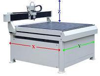 These machines are very efficient in that they work in all three directions in near perfect unison, giving this machine the capability of carving complex shapes.
The Components 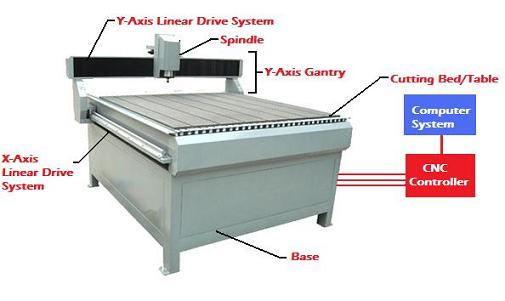 Lets look at these components in further detail.
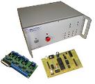
 The CNC Controller and Computer System Most designs start in a digital format such as a dxf drawing or some other similar format. The user would then use a CAM software package along with the CNC controller software provided. These types of software convert a 3D or 2D digital image into a tool path code such as G-code. The computer then converts these commands into a digital signal which it relays to the CNC controller which converts the digital signal to varying voltages and currents that control the mechanical drive systems. Most of this is far more than anyone operating a CNC wood router would need to know. It is usually plug and play. The user interface varies depending on the type or manufacturer, but the overall process is the same. You begin with a digital design and then use additional software to make tool paths for the machine to follow. The Spindle The spindle works bye rotating a cutting tool, such as router bits, at varying speeds. A typical spindle designed to cut wood plastics and other soft materials usually have a range of 8000 to 30,000 revolutions per minute. Spindles designed to cut metals operate between 2000 and 10,000 RPMs. Most CNC wood routers are capable of cutting metals as well. However, it is usually limited to non ferrous metals such as aluminum. When cutting metals or carbon based composites at high spindle speeds, a coolant system that cools the material being cut and the tool itself is usually necessary. Some spindles are controlled via the CNC controller which regulates the RPM based on material and the feed rate of the machine. There are other options that may be installed as well, some of which include an automatic tool changer, tool sensor, and touch probe. The Cutting Bed There are several different designs that do this effectively. Some of the most common cutting bed designs cutting bed designs are the T-slot, pictured above, and the vacuum table. The T-slot style table works well for most any part as it uses bolts and clamps to secure the piece to the bed. The vacuum table is found on many high end models and works well for companies cutting the same design several times a day. However, it is limited to relatively flat pieces such as wood and sheet material. The T-slot is more versatile in that is can hold virtually any piece but lacks in efficiency and speed of setup. There are many other types available, some are a hybrid mix employing both a T-slot and the vacuum design. However, these are the two primary types of cutting beds. The motor is the link between the mechanics and the electronics of the system. The motor receives its power via the CNC controller providing rotational power when needed to the lead screw assembly. 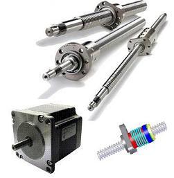 There are two types of motors found on CNC wood router machines, which are stepper motors and servo motors. Steppers motors are the cheaper alternative and offer good performance and reliability but are usually not a closed loop system. Servo motors offer a closed loop system, which means after receiving their directions from the CNC controller, they send a signal back to the controller that verifies they have completed the task.
 Closed loop systems are usually found on high end models. The type of controller depends on the type of motor. The controller for a stepper motor or a servo motor is not the same. The motor offers the power in the form of rotational motion which needs to be converted to linear motion. This is where the lead screw assembly takes over. Combined with a linear bearing assembly , the lead screw assembly moves the gantry or spindle along its axis. Different designs employ varying methods of converting rotational motion to linear motion and some are better than others. The most common are a lead screw and nut assembly, a ball screw and nut assembly, or a rack and pinion assembly. Each system has its own advantages and disadvantages but that information is too detailed for this section. However, you may find all this detailed information elsewhere in our site. Other Features Summary If you want more in depth information regarding any if these subjects and much more, check out the other sections of this website. Its all good information that can help you buy, build or just learn as much as possible about CNC wood routers. If you now have a basic understanding on how these machines work, lets continue on to the next section which takes a look at the different types and features that are available. |
The Builder's Guide
 Calculators
 CNC Controllers
 |
|
|
[?] Subscribe To This Site
Page Missing?Please bare with us as we upload pages. The website is still under contruction and new content is being added. To see the most recent pages, visit the website blog. Thank you! |
||
|
|
Homepage |
Buyer's Guide |
Builder's Guide |
Contact Us|
© Copyright 2007-2011. |
||
|
|
||


