 |
 |
|
Selecting a Leadscrew Part 1: The Must KnowsThere are a few criteria for selecting a leadscrew that should never be overlooked. However, some CNC router builders try and wing it when it comes to lead screw selection. Choosing the correct, diameter and lead are the most basic and crucial but there are other factors to consider as well. This section will cover the things you must know before proceeding to the actual selection of a leadscrew, which will be covered in Part Two. Weights You must know or be ready to estimate the weights of the individual moving assemblies. This is important in part 2. We will use these values to calculate the loads that the lead screw must withstand. Velocity and AccelerationYou must know the desired velocity at which you want your assembly to move. This is usually in inches per minute (IPM). You must also know the desired acceleration in (in/s/s), or the time at which you want to reach your goal velocity. It is much easier to estimate the time to reach velocity. Ex, I would like my machine to reach 200 IPM in .4 seconds. Length/SpanYou must know the total length or span of each leadscrew. It would also be helpful to know the maximum distance that the nut could be from the bearing support on each axis. Bearing Supports and End FixityAt this point of your biuld you might have some idea as to how you will secure the lead screw to the machine, but if not then no harm. Actually, it is best to fully understand how the different end fixity types will affect the outcome of your machine before choosing. There are four primary types of bearing supports. Reference the image below which represents the four bearing end fixity types. Shown least to greatest rigidity, from the top down. 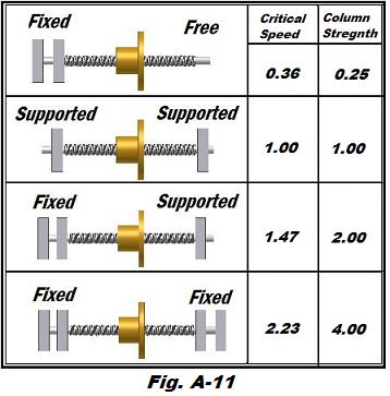 Supported- A supported end has a single bearing system. Fixed- A fixed system is either has the lead screw fixed in place (rotating nut), or there are two bearing supports spaced at least 1.5 times the diameter of the leadscrew shaft. Increasing the rigidity of the bearing support type will increase the critical speed and column loading capabilities. You do not always have to design around the most rigid. Actually, many diy CNCers, have a supported-supported type system. You just have to know the limitations each type places on you system, and not over load or over rotate the screw for that given fixity type. In the next paragraphs, you will see how the end fixity affects both critical speed and column strength. Critical SpeedCritical speed refers to the RPM at which the natural frequency of a rotating shaft begins. This vibration, also called resonance, will occur regardless to the orientation of the leadscrew. The critical speed also applies to rotating nuts about a lead screw. Some CNC router builders forgo calculating the critical speed. Then when it comes time for their machine to perform they will not meet their desired velocity. Here is how to calculate critical speed, although there is no need to do it now. That is one of the steps in Selecting a Leadscrew: Part 2. You may also use the Critical Speed Calculator . The formula for Critical speed is given below. The value of N is given below or may be found above in FIG. A-11. 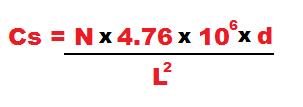 Given That: Cl = Max Load d = Minor Diameter of Screw L = Distance between nut bearing N = Fixity type = 0.25 for fixed-free = 1.00 for supported-supported = 2.00 for fixed-supported = 4.00 for fixed-fixed As you can see, as the rigidity of the end fixity increases, so does the critical speed. Always design so that the operating RPM is BELOW the critical speed . Column StrengthColumn strength refers to the maximum load a lead screw can withstand in compression before failing. Compression loads that exceed the column strength will cause the lead screw to buckle, or bend. Even the slightest bend can ruin a leadscrew. The formula used to calculate column strength is given below. You may also use the column strength calculator here. You do not need to calculate the column strength at this time. This is one of the steps in Part 2. Given That:
d = Root Diameter of Screw L = Length Between Bearing Supports N = Fixity Type = .36 for one end fixed, one end free = 1.00 for both ends simple = 1.47 for one end fixed, one end simple = 2.23 for both ends fixed Now that we understand lead screws, its time to choose one! Selecting a Lead Screw: Part 2 |
The Builder's Guide
 Calculators
 CNC Controllers
 |
|
|
[?] Subscribe To This Site
Page Missing?Please bare with us as we upload pages. The website is still under contruction and new content is being added. To see the most recent pages, visit the website blog. Thank you! |
||
|
|
Homepage |
Buyer's Guide |
Builder's Guide |
Contact Us|
© Copyright 2007-2011. |
||
|
|
||


