 |
 |
|
Buying a Stepper Motor DriverInterpreting the Stepper motor Driver Specifications The following descriptions are in no particular order. Not all sellers will provide all the specifications given below. However, some specifications can be determined through pictures or dedective reasoning. Number of axes: Some stepper drivers are multi-axis. Many of the stepper drivers used by hobbyist have three or four drivers and a breakout board combined for ease of use. This can be a good thing as it is more or less plug-and-play. However, be sure that it can handle your other input such as limit switches etc. I still prefer having the break out board and the stepper motor driver for each axis seperatly. Although there is more work up front when wiring, if one of your drivers fail, you do not have to replace the entire board. Phase Biploar and Uni-polar: Check to see if the stpper driver is single phase, two phase, uni-polar or biploar. For more detailed information on this read uni-polar vs bipolar drivers. Motor Compatibility: This is actually the same as above but just to clarify; A uni-polar stepper motor driver should be compatible with 5, 6, and 8 wire stepper motors. Bipolar drivers are compatible with 4, 6, and 8 wire motors. Of course the number of leads alone does not ensure compatibility between motors and drivers. Current type: This is almost not worth mentioning but be sure that the driver is direct current (DC). Although rare, there are some alternating current (AC) stepper drivers available. Input voltage: Check the maximum and minimum input voltage for the driver. This, along with your motor power rating, will help you size the power supply needed. Current Output rating: 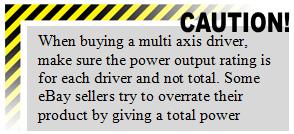 The driver should always specify the current or power output rating for the driver. Most times it is given per phase, such as 3 amps per phase. It should also specify the minimum output per phase. This is one of the most important specifications because it determines the size of stepper motor it can drive.
Current Adjustability: Most stepper drivers allow the user to adjust the maximum power supplied to motor by adjusting the current. This is usually achieved by changing an on-board resistor or by an adjustable resistor (potentiometer). This is a nice feature to have as it allows you to choose a motor more tuned for your needs. Command Signal Input Type: For CNC use, you should look for a Step and Direction input type. This is the most common however some robotics applications use different command signals, so always be sure to check. More on command signals may be found here. Some drivers have several modes of operation, full step, half step, and micro-stepping. Be sure to check and see which step modes are offered. More on stepper motor driver modes may be found here. Driver Type: The driver should specify how it powers the motors. It should be an L/R driver, bi-level driver, or (PWM) Chopper driver. If it does not specify assume it to be a chopper or (PWM) driver as that type is common. More on driver types may be found here. Switching Speed: (PWM drivers only) The specifications may give the switching speed of the chopper driver. Not to be confused with step frequency, the switching frequency is the frequency at which the PWM driver operates. This value should be at least 20 kHz. The higher the frequency, the more smoothly the driver will operate. Step Frequency: This is the maximum input frequency for the command signal. A good driver will have an input frequency of 0 to 200 kHz. This is important if trying to achieve high speeds and high accuracy. More on command signals may be found here. Protection Circuitry: Most drivers offer internal circuitry protection to safeguard the motors and signal generator or computer. This is achieved through the use of opto-isolators and fuses. If the driver offers not protection, make sure that the break out board does. Idle Standby Feature: Some drivers offer a standby feature that reduces the power supplied to each stepper motor after being idle for a certain amount of time. This helps reduce stepper motor heat which can increase the life of the motor and help motor efficiency. Conclusion: There are certain feature that are specific to each driver and thus to many to cover. However, all stepper motor drivers should have the above in common. If you are aware of the above features then you should do well when choosing a stepper driver. Back: to CNC Controllers |
The Builder's Guide
 Calculators
 CNC Controllers
 |
|
|
[?] Subscribe To This Site
Page Missing?Please bare with us as we upload pages. The website is still under contruction and new content is being added. To see the most recent pages, visit the website blog. Thank you! |
||
|
|
Homepage |
Buyer's Guide |
Builder's Guide |
Contact Us|
© Copyright 2007-2011. |
||
|
|
||


